Sponsored by:

Designing a Sustainable and Affordable Cooling Technology for Mattress
Cameron King, Dio Oey, Lakshmi Prerana Panchumarti, Elijah Tan., Thomas Thwaite, Wendi (Allen) Wu

Air flow
Testing description
Air flow is crucial to determine cooling capabilities of a mattress. Increased air flow allows for heat to be carried away from the user via convection. Mattresses with bad airflow trap heat, making the user feel hot. The most common method for determining air flow is to measure the flow rate of air through a known sample area. Most companies use ft/min to measure the speed of air going through the mattress. When airflow is bad, heat is trapped within the mattress and so users will feel hot. Materials that show good airflow capabilities generally have larger porosity thus allowing air to pass through easily.
There are numerous ways to measure the airflow of a sample. In industry, specialized equipment is used. Because we did not have access to standard equipment, modified test methods following the concepts used in the standards were developed (Appendix C-1). equipment We first tested each component, ensuring that each component was breathable. Once the air flow rates of each component were determined, a larger apparatus to test the prototype was built.
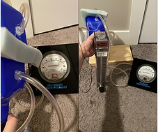
As shown in Figure 3, the air flow apparatus consisted of a flow tube with 2 funnels of the same size and shape. One hole was drilled on top of each funnel to attach tubes to it. The tubes were then connected to a pressure gauge to measure the pressure at each funnel. One end of the funnel was connected to a flow tube whereas the other end was connected to a vacuum. The sample went between the 2 funnels and was secured using tape to prevent lateral air leakage. The vacuum pulled the air through the sample and measured the flow rate once a constant pressure differential was reached, as shown on the pressure gauge. This test was done on 4 types of foam (pneumatic, control, cooling, and latex), and on 4 different matrix combinations.

Figure 3: Larger air flow test apparatus developed to test the prototype.

C-1: Sheffield Air Porosity meter, the wood is to prevent air from escaping laterally and air flow is measured using a flow tube.
C-2: Air Flow measurement taken using 2 funnels connected to a flow tube and pressure gauge. Pressure gauge is connected using a glue gun to prevent air leakage. Funnel is connected to a vacuum, and reading are recorded when constant differential pressure achieved

Result


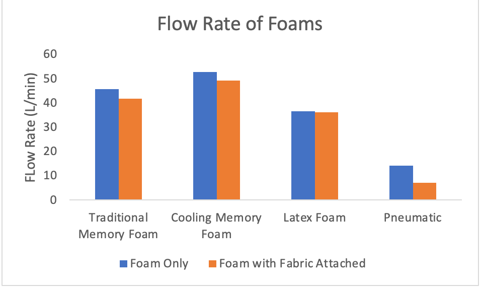
To determine which foams are used for the matrix prototype, each foam was tested individually to analyze the flow rate. All 4 foams were exposed to air flowing at a rate of 56.4 L/min and the flow rate through each foam was recorded when a constant pressure differential is achieved. Figure 6 shows the results of airflow for each test sample. The blue bars represent foams without mesh wrapped around them, whereas the orange bars represent airflow values for the foams with fabric wrapped around them. From the data, we observed that the fabric wrapping decreases the airflow of foam only by a minimal amount. Thus, using fabric will not impede air flow by much and can be used as an enclosure for the silicone matrix.
We also observed that traditional and cooling memory foam exhibited the best air flow properties among the 4 types of foam having air flow rates of 45.8 L/min and 52.85 L/min respectively. Possible reasons behind this result may be due to the microstructure of the foam, where the larger the porosity the higher the flow rate for the foam. Latex foams also displayed good air flow at 36.5 L/min with comparable values to the traditional and cooling foams. However, it must be considered that latex foam tested has large holes cut into the foam for breathability, so the value recorded for these specific samples might be inflated over latex foam without holes. The pneumatic foam shows the lowest air flow property with a measurement of 14.15 L/min. This may be attributed to the foam being denser than the others, thus reducing the porosity and impeding more air. From this data, it can be concluded that traditional and cooling memory foams are the best choices for airflow properties. Latex foams can also be considered as having good air flow as it had comparable values to traditional foam and is more environmentally friendly.
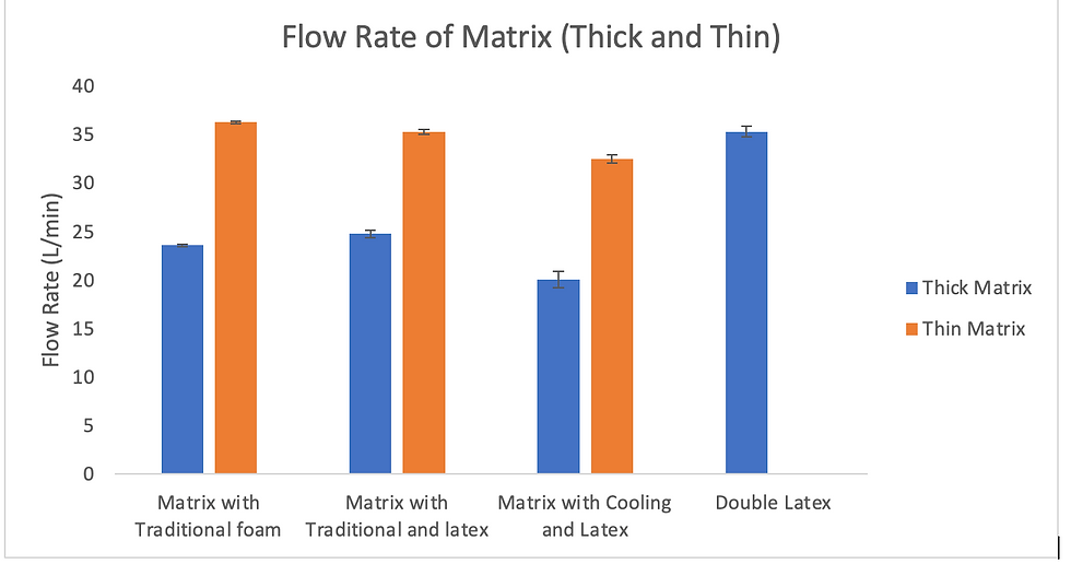
Flow rate of different combinations of foams with matrix are measured. Three different combinations are made. 1st is matrix coupled with traditional foam, 2nd is matrix coupled with traditional and latex foam, 3rd is matrix coupled with cooling foam and latex foam. These three combinations are compared with the air flow of double latex as a benchmark for airflow values. Latex is chosen as a benchmark due to it being a sustainable foam while still having good air flow properties. The 1st combination is the prototype matrix (thick or thin) paired with two traditional foams. 2nd combination is the prototype matrix (thick or thin) paired with traditional foam on the bottom and latex foam on the top. The 3rd combination involves the prototype matrix (thick or thin) paired with double cooling foam. The blue bars represent combinations using the thicker matrix, whereas the orange bars represent combinations using the thinner matrix. It is important to note that the thick silicone matrix is filled with shredded foam to minimize shearing and increase comfort.
From the testing of thicker matrix sample (blue bars), it was observed that the 2nd combination including traditional, and latex has the highest airflow property. This may be because the latex foams have large holes, increasing the air flow. Similarly, the flow rate for the thin matrix showed that matrix with traditional foam (1st combination) has the highest air flow, followed by traditional and latex (2nd combination) and cooling and latex (3rd combination). The results don’t show significant differences and each airflow rate was comparable to each other. This may be due to the thin matrix having larger holes and not filled with shredded memory foam, thus making flow rate higher.
Some sources of error in this experiment are that it is not a completely closed system. To minimize air leakage, the foam is taped to the funnel and compressed. By compressing the foams on the outer edges, air leakage from the sides can be minimized. Additionally, the funnels are taped to the vacuum, thus there might also be some leakage through the funnel hole. Another possible source of error is inaccuracies in reading the flow tube due to a lack of range in the reader. The flow tube uses a ball instead of an arrow to display the measurements, which tends to give more vague results when compared to a line reading.
From the results, the matrix with shredded foam and nets experiences a reduced airflow. When compared to the other 4 foams, the matrix combination shows higher airflow than pneumatic foams. This may be attributed to the shredded foam filler in the matrix. The shredded foam can impede airflow, making the airflow significantly less. However, the values are still acceptable as it has a higher air flow rate than pneumatic foams commonly used in the market.